Homecoming Engineering
Arduino Micro-Controller Orchestration: Raspberry Pi’s I2C Communication.
Table of contents
About
I created this project to provide further instruction for future engineers working on the homecoming engineering team. The homecoming deck motor design consisted of a Raspberry Pi controlling Arduino’s that were paired to relay’s that triggered to enable motor movement.
This is supposed to be a starting point for setting up development utilizing a Raspberry Pi and Arduino’s paired over I2C.
We recieved the award for the Best Engineering Team and Design, judged by University CEAT (College of Engineering, Architecture, and Technology) professors and colleagues, for my newly designed system for controlling the moving parts on the homecoming deck.
How It Started
I was assigned to lead the engineering team for my fraternity in homecoming. One of our main jobs is to create and operate all of the moving parts for our homecoming deck. In the past, the teams solution to this was to use separately programmed Arduinos that were used to individually control motors. Timing is key to this method, as they have to start the devices all at the same time so that the moving parts on the deck run simultaneously. They were programming the arduinos with seperate code with different time intervals for each device. When I realized this is what they have been doing in the past, it made me wonder if there was a better solution to this problem.
I already owned my own Raspberry Pi, so I started doing some research on communication between the device and other micro controllers. I read about some projects using the I2C (Inter-integrated Circuit) communication protocol for both devices, but a lot of the information I found was not very “beginner friendly” and/or it lacked in-depth information. I was able to create a prototype on my own after a few days of work, but I wanted to make it easier for future developers looking for I2C guidance.
Development
Setting up the Raspberry Pi Environment
First, we have to setup our Raspberry Pi with Rasbian and a Python IDE. There are plenty of tutorials and videos on how to do that online, so I won’t explain that here.
After you have setup Rasbian, we need to enable the SSH client on the Raspberry Pi. This will allow you to access your Raspberry Pi remotely if you are connected to the same WiFi as the Raspberry Pi.
- Open up the terminal window and type:
sudo raspi-config
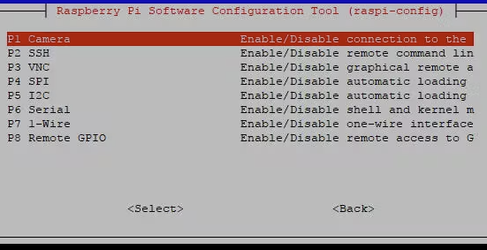
- Go into the Interfacing Controls option:

- Go into the SSH tab, and click to P2 SSH and enable it:

Now that your Raspberry Pi is setup for a remote connection, you can download applications like “PuTTy” on your laptop to access the device. To do this you need to find the IP address of your Raspberry Pi.
- Go back into the terminal window on the Raspberri Pi and enter the command:
sudo ifconfig
The IP address you need is labeled as “inet addr:123.45.678.901”.
When you setup PuTTy on your laptop this is the IP address you will use to access the Raspberry Pi. You will then be prompted with a sign in screen.
The default username and password for every Raspberry Pi:
- Username
- pi
- Password
- raspberry
You will use this environment later when you have completed the rest of the tutorial.
Setting up the I2C Protocol
This step is to setup the Raspberry Pi so it can communicate with the Arduinos via an I2C bus.
- Open a new terminal window and type in the following to install SMBus and necessary libraries:
sudo apt-get install python-smbus python3-smbus python-dev python3-dev
- Type in the following to install the I2C libraries:
sudo apt-get install i2c-tools
- Type in the following to open the raspi-blacklist configuration to enable I2C and SPI protocol:
sudo nano /etc/modprobe.d/raspi-blacklist.conf
In the file you should see two lines:
#blacklist spi-bcm2708
#blacklist i2c-bcm2708
Delese the # in front of both of these lines, press control X to save and exit from the file.
- For recent versions of the Raspberry Pi, you will need to edit the boot configuration file to enable I2C and SPI protocol:
sudo nano /boot/config.txt
In the configuration file, add these two lines to the bottom of the file:
dtparam=i2c1=on
dtparam=i2c_arm=on
Again, save and exit by pressing control X.
Now your Raspberry Pi is ready to utilize the I2C protocol to communicate with other devices.
Hardware Connections and Schematics
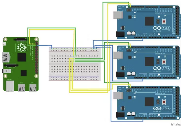
Here are schematics for the Raspberry Pi, Arduino’s, relays, and developmental boards.
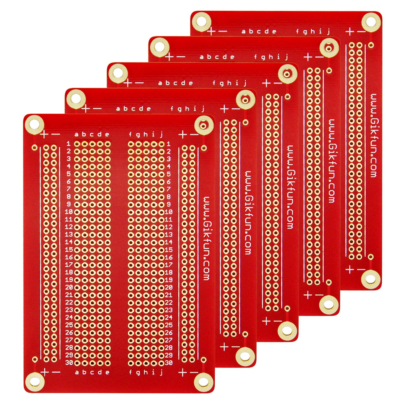
Preferably, for more solid and stable connections, you will need to use a solderable board for connections to the relays and Arduino’s.
For the I2C breadboard connections, you will only need to use the jumper wires for the connections from the Raspberry Pi to the breadboard.

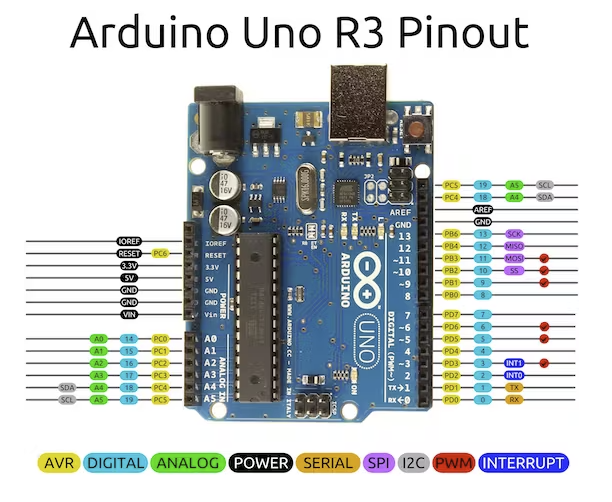
The Arduino boards pictured above are Arduino Mega’s. The ones I used for this documentation were Arduino Uno’s whose pins were slightly different. The correct I2C pins on the Arduino Uno are pins A4 and A5 pictured below:

For connecting the relays to each Arduino I used solderable boards to ensure that I would not have any loose wires.

The forward and backward relays for your motor would be connected to pin 10 and pin 11 respectively.
The Code
The provided Python code for the Raspberry Pi is my testing code for my project. This allowed me to test all of my Arduinos and relays connected to them. I tried to make it user friendly so that the other engineers can run the program when I am not around.
Raspberry Pi Test Code
from smbus import SMBus
import time

addr = 0x5
bus = SMBus(1)

# Time delay (Seconds)
timeup = float(5.0)
timedown = float(5.0)
timedelay = float(1.0)

# Main function
def main():
    # Tests the relays to make sure they are connected properly
    bus.write_byte(addr, 0x0)

    bus.write_byte(addr, 0x1)
    time.sleep(timedown)
    bus.write_byte(addr, 0x0)
    time.sleep(timedelay)
    bus.write_byte(addr, 0x2)
    time.sleep(timeup)
    bus.write_byte(addr, 0x0)
    time.sleep(timedelay)

def up():
    timeup = float(1.0)

    bus.write_byte(addr, 0x2)
    time.sleep(timeup)
    bus.write_byte(addr, 0x0)

def down():
    timedown = float(1.0)

    bus.write_byte(addr, 0x1)
    time.sleep(timedown)
    bus.write_byte(addr, 0x0)
Arduino Test Code
#include <Wire.h>

#define forward 10
#define backward 11

void setup() {
  Wire.begin(0x5); // join i2c bus with address #5
  // Wire.begin(0x6); // join i2c bus with address #6 (2nd arduino)
  // Wire.begin(0x7); // join i2c bus with address #7 (3rd arduino)
  // Wire.begin(0xN); // join i2c bus with address #8 (Nth arduino)
  Wire.onReceive(receiveEvent); // register event
  pinMode(forward, OUTPUT);
  pinMode(backward, OUTPUT);
}

void loop() {
  delay(100);
}

// function that executes whenever data is received from master
void receiveEvent(int howMany) {
  while (Wire.available()) { // if wire connection is available
    char c = Wire.read(); // receive byte as a character

    if (c == 1 && c != 2){
      digitalWrite(forward, c); // sets the forward relay to close when input is 1
    }
    else if (c == 2 && c != 1){
      digitalWrite(backward, c); // sets the backward relay to close when input is 2
    }
    else{
      digitalWrite(forward, c); // resets both relays to remain open when input is 0
      digitalWrite(backward, c);
    }
  }
}- The address assignments are the addresses for each Arduino that is connected to the Raspberry Pi:
addr = 0x5
addr2 = 0x6
addrN = 0xN- Writing to the bus, we will send 0x0, 0x1, and 0x2 values to tell the motor to stop, move forward, and move backward respectively:
bus.write_byte(addr2, 0x2) # Motor moves backward.
bus.write_byte(addr, 0x1) # Motor moves forward.
bus.write_byte(addr, 0x0) # Motor stops movement.
Operating the Program
Once you have uploaded your code and your wiring is secure, log into the Raspberry Pi terminal and type the following code to scan for the Arduino:
i2cdetect -y 1
You should see the address (0x5, 0x6, …0xN) the Arduino is connected to in the list. This shows us that our connections are secure and the devices are ready to talk to one another.
Now run the Python program on your Raspberry Pi:
python3 test.py
If everything is working correctly, your relays will close and open depending on which the test parameters that are chosen.
Conclusion
Hopefully this helps some people out there who are looking for a more indepth instruction for using I2C connections. You can alter the code I provided to suit your needs in your DIY projects at home. The options are endless.
